Showing posts with label Power. Show all posts

Thursday, 31 January 2013

Episode 12: A Side Project

As you may be aware I’ve been toying with the notion of a side project, based upon the inspiration of some of Epping Railway Circle’s end to end (or shelf – this will become an important word later on) layouts, like this one…


So far my current layout has developed from concept…

To construction…


To something that really is starting to look rather good.


If you track back to Episode 2, you’ll remember I set myself the task, amongst others, that my layout should be easy to set up and set down. This was, at the beginning, achieved successfully. However as I’ve done more, and added scenery and buildings that can be plopped down the set up and set down time gets a little longer each time. In reality there is never going to be a fast and easy solution to setting up and setting down any model railway that isn’t a permanent fixture. Especially as in my case I’m quite particular in making sure all the trains go back into their correct boxes (must’ve inherited this trait from my Dad) and all the buildings are stacked such that they’re not going to damage each other in storage. 

Now, this isn’t as big a problem as I’m making it sound. I actually quite enjoy the fact it takes a bit of time to get everything set just so. Equally as sad I also enjoy making sure everything is packed away in it’s appropriate place too, right down to putting the boards back in the cupboard; it makes me feel like I’ve successfully achieved some of my targets of this project.
What I will say is, that because setting up and setting down is a now a more lengthy process I feel more obliged to get the layout out when I know I can dedicate a weekend, or a run of days off to its use and continued construction. One day, this will not be a problem when I hopefully don’t have an as busy flat and have maybe some more space at my disposal. It would be really great to have something much smaller that doesn’t need a weekends dedication...

Don’t get me wrong, this is not an abandonment of my original project by any mile, quite the contrary, as I have some updates for you on that front from what I have worked on recently. This side project is also a chance to explore making a more of a model scene, rather than somewhere to enjoy running all the various trains I like. By this I mean there is more potential in a smaller shelf layout to explore things like setting, era and theme. After all, on an end to end layout it’s not possible to set a train going purely for the enjoynment of watching it run. The enjoyment in a shelf layout is different - there’s scope for operational planning, shuffling wagons about mimicking real life scenarios.
So here we go, rather than taking months to tell you where I’m up to on this project, most of the techniques I have already done so rather than taking months to explain where I’m up to, I will update you more swiftly…


Here’s the design. I agonised over this for quite a while, and maybe there is scope for a separate blog of how many versions of this plan I went through until I got to this one…

The dimension is 120 cm x 30 cm, why will become clear shortly.

It will feature:
  • A small terminus station, which could either be a rural location of forgotten inner city branch.
  • A number of sidings and head shunts. These will all comfortably accomodate a 2 car Pacer DMU or a tank loco + coach by design, meaning I can give this either a modern or historical setting, or preferably something neutralish so I can chop and change.
  • An out of sight ‘fiddle yard*’ (the red line) where trains will appear to vanish up the main line and into a tunnel.
*Fiddle yard is a term used by model railwayers to describe a set of sidings or track out of sight from the rest of the layout. They are usually un-landscaped and hidden in such a way to maintain the illusion of a setting for the rest of the model.


A trip to B & Q and I come back with this. It is, rather unsurprisingly, a 120cm x 30cm pine untreated shelf. (Shelf being a key word remember). This will act as my baseboard.

The track fits on it thussly…

You’ll be wondering why these dimensions?

My desk is exactly 120cm long, as is my coffee table (nearly). It’s also relatively small and inoffensive so storage is going to be no problem at all, but it’s going to be easy to move about and I can plonk it in more places when in use.


This time I wanted to explore the use of motorised points. Therefore I’ve raised the baseboard up by putting it on a ‘frame.’ And by ‘frame’ I mean two pieces of strip wood. I nailed the shelf to these.

Completed baseboard on frame.
I can confirm that pine will accept track pins with ease, as will it accept drilling: to come later…

I have however elected to lay down some cork on top of the baseboard which will hide the nails of the frame and also provide a uniform surface for everything else going on top.

Some modellers will find proper cork sheets. Me? I’m using floor tiles. They’re even slightly laminated which will later prove helpful when sticking things to it… They’re also rather brilliantly (roughly) 30cm x 30cm meaning I’m not going to have to cut a great deal!

PVA glue (100% as opposed to a mix with water) will do just fine here.

This time, whilst laying the track, I have drilled holes as I go for track power supplies and points. A good tip I picked up on the forums was to pre solder power supply lines to the fishplates, this will help you not melt the sleepers as I did in my other layout…

This partly worked… It would have worked better if I wasn’t using utterly rubbish solder but it did involve snapping off a bit of sleeper from some track which you’ll see in following photos.

Once this was all complete I added some point motors.

Now, I could take up a whole blog talking about point motors. They come in a variety of flavours and costs. Most modellers will opt for something that is fitted underneath the board, some even go the whole hog with wires and pulleys mimicking signalling systems of days gone by.

As this is my first go, I’ve opted for surface mounted point motors. Peco PL-11’s to be precise. They are really simple to fit - simply latch onto the side of your point and nail down. A small hole will be required for the wires to disappear under your board. (Hence the frame). Most modellers will opt for something more discrete but this is my first attempt after all.

Again you can go and get really cheap switches but I’ve elected to get the more expensive Hornby ones. This was in part because they give a much nicer, and more authentic, signal cabin lever experience but partly because they are much easier to wire.

I could go into much more detail, and maybe I will do a dedicated post about the point wiring  at some point, but essentially for PL-11: You connect the red and black wire to the switch. These dictate which way the point sets. You then connect all the green wires (these are your commons) to one side of your power supply. The other side of the power supply feeds power to the switches. In the above picture, this one is brown, but it quite hard to see.  Again, I will properly explain this all at some point. There are also good places to go to explain how to do it… Like here

Rather excitingly, all the points worked straight away! Very pleased with myself.


Wiring takes shape underneath.

Next up it’s time to start adding some ballast. Check out This Episode for a more detailed breakdown.
I’ve used a slightly different colour than before. I’ve also stuck down the platform and buildings here using some super glue.

After another trip to B & Q, I’ve obscured the fiddle yard using some strip wood. I’ve also taken the opportunity to build a bridge for some added scenic interest. (I’m going to talk more about the decisions I’ve made on the landscaping in future blogs).
Another view, the mainline disappearing into the ‘tunnel’ on the right. Cleverly hidden by the strip wood.


And that’s where we’re up to!


Wednesday, 12 December 2012

Episode 11: Powerrrrrrrr


As the great Jeremy Clarkson once said, 'Powwwweeerrrrrrr.'

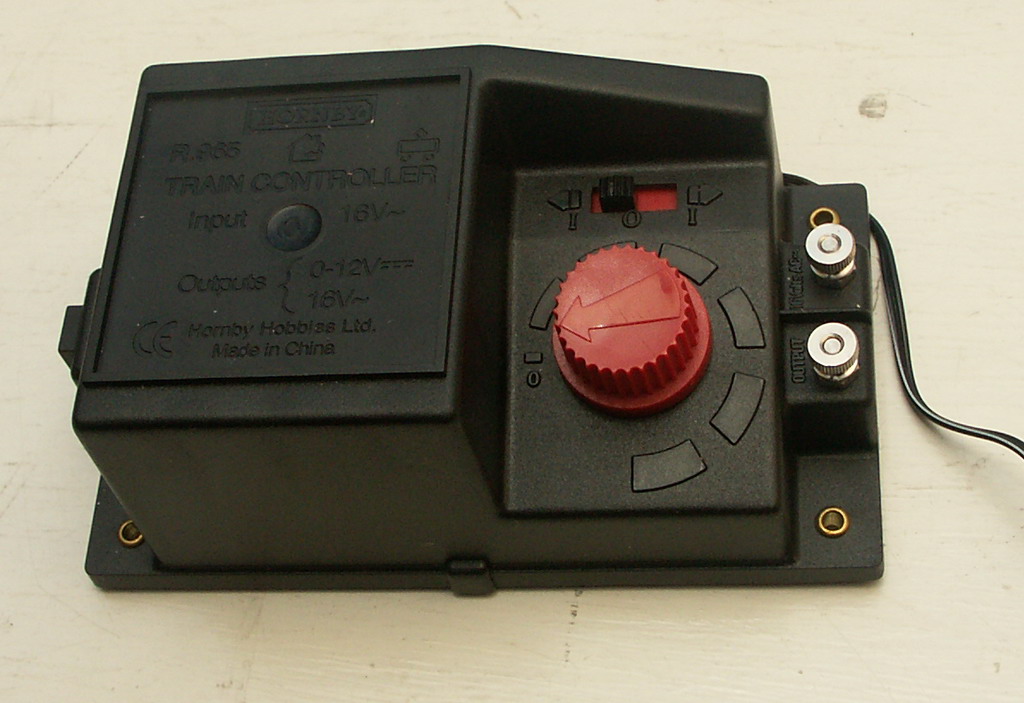
Back in't'day... there was only one way to power your model railway. A good old Analogue potentiometer took care of business. You can go faster. Or you can go slower. One train and one controller per track. Simple. 


More recently however the model railwaying world has been taken a storm by DCC (Digital Command Control). I'm not going to go into detail, because you can catch me chatting about DCC in Side Tracked 1 of this blog, but DCC allows for multiple trains per track, plus an array of extra such as lighting and sound via one control unit. Sounds great, but it is more expensive and you will have to convert your existing locos with special decoder chips.


One day I will invest in DCC and possibly convert some of my older stock but right now we'll look at a couple of power issues on my good old Analogue layout.

Isolation:

First an issue with Isolation. DCC layouts can support multiple trains on the same track due to given every loco a code and powering that code accordingly. With an analogue layout, you don't have this luxury and 9 out of 10 times the golden rule is: one train per track/loop and one train per power supply


You can of course, like I have, design your layout to have multiple loops to accommodate additional trains which can be isolated from the power supply and swapped as desired. This works perfectly well for certain point setups...

When Point C and Point D are set in favour of the Outer Loop you are isolating the outside rail of the Inner (Orange) track. Locos must receive power on both rails to work, therefore by setting C and D in this way you have definitely broken part of the circuit on the Inner (Orange) loop and your train doesn't move. Conversely you can set C and D in favour of the Inner (Orange) loop and this Isolates the Outer Loop allowing for aforementioned train swapage. Forgive me if this is simple stuff but it helps explain the next part a bit better. 

My plan was to deploy a similar tactic for the Blue section of track, isolating a train here allowing A and B to be set to allow access to the centre siding from the Outer Loops. This is essential for maximising stock on the layout. As the following diagram will illustrate this plan was slightly flawed... 


Even with points A and B set in this way the Blue section of track is not isolated. Wherever you place a locomotive on the oval it will still pick up power from 'Power Supply 1.' You can check this by choosing a point on the oval and see if the red and green lines end up at the purple box (Power Supply 1). And they always do.

We therefore need to create a break in either* the Red or Green line in the Blue section of track which we want to isolate.

*Remember we only need to break one rail for the locomotive not to be part of the circuit. 


Thankfully - this is painfully simple. 

Carefully lifting up the track I was able to remove both fishplate connections just to the right of 'Point B.'

This achieves a physical break in the track. Don't worry though, as long as you are accurate with your nailing (back) down the track is still aligned and this doesn't affect the running of your trains when you DON'T want to isolate this section.

When you do however, you'll notice that in the Blue section of track the Red line (rail) is now disconnected from Power Supply 1. 

You can now safely put a train in this section whilst you move another out of the centre siding. 

A similar tactic was also employed just to the right of Point C (above). 

Some modellers will add additional isolation points and purposefully reconnect them via an on/off switch. This gives them the option to turn power on and off to sections of continuous track should they so desire.

This is something for me to consider in the future, but currently it is not required on a layout of this size.

Getting Power To The Track:

The second thing I've done that relates to Powweerrrrr isn't so much an issue but more of a way of making the layout look neater. It does also help in set up/down.


Here was what I was using before...

This is the 'Hornby Power Clip.' You plug in your power supply to the points A/B (above) and it slots into the side of your track. This is fine for those starting out, but I find them unsightly, unreliable and restrictive of at which spots on your track they can be slotted into. 


This is how they looked on my layout. I found that once you had a wire plugged into this one (above) on the inner loop, it was encroaching and restricting the loading gauge of trains on the outter loop. Securing the wire from not getting caught up in the trains on both loops was also becoming a problem.

  
This (above) - killed two birds with one soldering iron. And some wire hooks.

Quite simply - I've soldered the wires straight onto the track. Then using wire hooks nailed the wire down to keep them away from trains. Eventually I will paint these black, and I think they will look like quite realistic lineside cabling! (Hopefully no OO scale people will come and steal it...).


I found it easiest to feed wires under track under fishplate joins. 

It may be worth removing a couple of the plastic sleepers where you intend to solder the wire to the track. I found it hard to avoid them melting.... The track is tough though and will accept the heat without buckling. Other modellers will solder the wire to a fishplate first, and then reconnect the fishplates to the track. This avoids being near any melting sleepers when soldering... But this sounded fiddley, so I didn't bother. 

  
To complete the setup I ran the wires under the join and then along the side of the board. The controllers are then plugged in just out of sight on the right.


Next time I'm going to talk a little bit about adapting points to help reduce derailments. 


Wednesday, 7 November 2012

Episode 10 ½: Layout In Operation 04/11/12

A little video of the layout in operation. Hopefully displaying what the pictures can't.


Things to note:
  • I've added more scenic scatter (the greens and browns) which now covers most of the board. The brown area is intended to be 'yard access' from the main streets. I want to add different colour browns at a later date to make this look more realistic.
  • The addition of some denser/'clumpier' scatter has been added to create the affect of hedge rows. These have also helped separate track bed from grass in a much neater manner. More of this will be added in other areas soon.
  • The gap in scenery at the bottom left of the video, as mentioned in previous Episodes, has been left for a potential level crossing.
  • There is some new cabling shown bottom left. This is a more permanent track power fixture which I will explain in upcoming episodes.
  • Watch out for the de-railing wagon about half way through! And the dodgy camera angle as I try to hide re-alligning it. I'm investigating as to why this occasionally happens.